Example 87h: Photonic Switch |
||||||||||||||||||
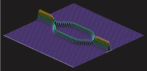
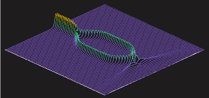
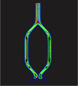
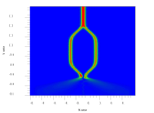
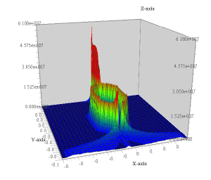
| This example illustrates some of the waveguide capabilities
in GLAD. GLAD performs detailed modeling of 2D and 3D waveguides
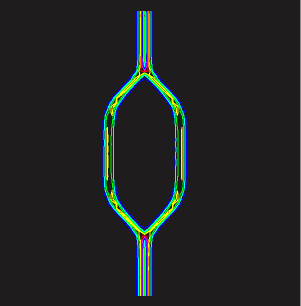
using the beam propagation method (BPM). In this example, a higher index
guide region is split into two paths and, after some distance,
the two paths are rejoined to form the equivalent of a Mach-Zender
interferometer. Light injected into the waveguide at the upper left
follows the waveguide, splits into to parts, and then recombines
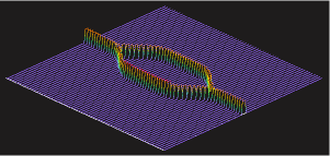
when the paths rejoin. If the optical path length of the two
paths is identical the interference is constructive and the switch is
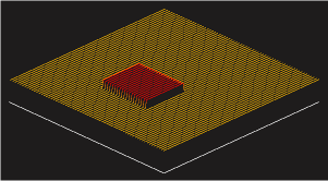
"on". The switch may be turned "off" by raising the index of refraction
in one of the legs by using an electro-optic effect to achieve a 180
degree change in optical path length.
You may "expand" or click on the image to see a high resolution Scalable Vector Graphic (SVG) image. You will need to have the free SVG plug-in installed in your browser. www.adobe.com/svg/
|
![[lines forming waveguide]](ex87h_1.gif)
